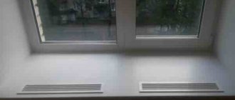
Purpose
Led-driver is a stabilizing module. Without it, none of the currently produced LED elements can work - from the weakest to the most powerful. It must be strictly selected for the load of the assembled circuit, especially when the luminaires have a serial connection. In this case, the voltage drop in each specific led light source can vary (as it depends on the factory assembly parameters), while the current strength should remain the same for all of them.
The role of the led-driver simply cannot be overestimated. After all, with the slightest increase in power supply parameters, the semiconductor crystal instantly heats up and burns out. On the other hand, when the network characteristics drop, the light output suffers and the aperture ratio declared by the manufacturer decreases. That's why it's so important to choose the right driver for LEDs.
LED driver lifespan.
There is no specific service life as such, but many manufacturers are willing to provide a five-year warranty on their products. Naturally, upon coordination of capacities. In order for the power source to last longer, you should not provide a load at which it will deliver maximum currents. If it is assembled from high-quality components, it will work stably for quite a long time. But operating temperatures can be close to critical (depending on circuit design solutions). It is optimal if the power of consumers is 20-30 percent less.
If we are talking about homemade production, then a lot depends on the quality of the assembly and the quality of the radio components. It is advisable to attach integral stabilizers to a radiator to ensure thermal conditions; do not forget about the heat-conducting paste between the stabilizer body and the heat sink.
- Related Posts
- How does an LED lamp work?
- Device and connection diagram of the DRV 250 lamp
- Tips for choosing 12 volt lamps
Principle of operation
The main purpose of the led-driver is to maintain the stability of the output current. Drivers for led elements produced today are mostly assembled on the principle of operation of pulse-width converters. They include a pulse transformer and current-stabilizing microcircuits. Such devices are designed to be powered from a household network with a voltage of 220 volts, are characterized by a high efficiency index and have a special fuse against overload and short circuit.
There are also linear type LED-drivers. The principle of its operation is based on stabilizing the current as it passes through a transistor with a p-channel. Unlike the modification described above, it is a cheaper, simpler and less efficient analogue. During operation, such drivers can become very hot, and therefore are not used for circuits with powerful LED elements.
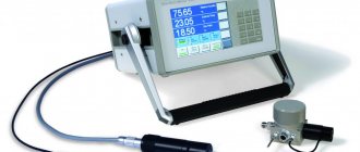
Rules for selecting a current converter
To purchase an LED lamp converter, you should study the key characteristics of the device. It is worth relying on the output voltage, rated current and output power.
LED power
Let us initially analyze the output voltage, which is subject to several factors:
- the value of voltage loss at the PN junctions of the crystals;
- number of light diodes in the chain;
- connection diagram.
The parameters of the rated current can be determined by the characteristic features of the consumer, namely the power of the LED elements and the degree of their brightness.
This indicator will affect the current consumed by the crystals, the range of which varies based on the required brightness. The task of the converter is to provide these elements with the required amount of energy.
The output voltage value must be greater than or identical to the total amount of energy expended on each block of the electrical circuit
The power of the device depends on the strength of each LED element, their color and quantity.
To calculate the energy consumed, use the following formula:
PH = PLED * N,
Where
- PLED – electrical load created by one diode,
- N is the number of crystals in the chain.
The obtained indicators should not be less than the driver power. Now it is necessary to determine the required nominal value.
Maximum power of the device
It should also be taken into account that in order to ensure stable operation of the converter, its nominal values must exceed the obtained PH value by 20-30%.
Thus the formula takes the form:
Pmax ≥ (1.2..1.3) * PH,
where Pmax is the rated power of the power supply.
In addition to the power and number of consumers on the board, the load strength is also subject to the color factors of the consumer. With the same current, depending on the shade, they have different voltage drops.
The driver for the LED lamp must supply the amount of current necessary to ensure maximum brightness. When selecting a device, the buyer must remember that the power must be greater than what all LEDs use
Let's take, for example, LEDs from the American company Cree from the XP-E line in red.
Their characteristics are as follows:
- voltage drop 1.9-2.4 V;
- current 350 mA;
- average power consumption 750 mW.
A green analogue at the same current will have completely different indicators: losses at PN junctions are 3.3-3.9 V, and the power is 1.25 W.
Accordingly, we can draw conclusions: a driver rated at 10 W is used to power twelve red crystals or eight green ones.
LED connection diagram
The choice of driver should be made after determining the connection diagram for LED consumers. If you first purchase light diodes and then select a converter for them, this process will be accompanied by a lot of difficulties.
To find a device that ensures the operation of exactly this number of consumers with a given connection diagram, you will have to spend a lot of time.
Let's give an example with six consumers. Their voltage loss is 3 V, current consumption is 300 mA. To connect them, you can use one of the methods, and in each individual case the required parameters of the power supply will differ.
The disadvantage of alternating diodes is the need for a higher voltage power supply if there are a lot of crystals in the circuit
In our case, when connected in series, an 18 V unit with a current of 300 mA is required. The main advantage of this method is that the same power passes through the entire line, and accordingly, all diodes burn with identical brightness.
The disadvantage of parallel placement of consumers is the difference in the brightness of each chain. This negative phenomenon occurs due to the scattering of diode parameters due to differences between the current passing through each line
If parallel placement is used, it is enough to use a 9 V converter, however, the consumed current will be doubled compared to the previous method.
The method of sequential arrangement of two diodes cannot be used with a change in the number of crystals included in the group - 3 or more. Such restrictions are due to the fact that too much current can pass through one element, and this creates the likelihood of failure of the entire circuit
If a sequential method is used with the formation of pairs of two LEDs, a driver with similar performance is used as in the previous case. In this case, the brightness of the lighting will be uniform.
However, even here there are some negative nuances: when power is supplied to the group, due to the variation in characteristics, one of the LEDs can open faster than the second, and accordingly, a current twice the nominal value will flow through it.
Many types of LEDs for home lighting are designed for such short-term surges, but this method is less popular.
Main characteristics
Among the main characteristics of the led-driver, the following three are of particular importance to its operating parameters:
- Output voltage.
- Rated current.
- Power.
The first factor is influenced by the voltage drop of the ice element itself, as well as the method of its connection. If a parallel circuit is used, then the voltage on all LEDs will be the same. The result will be different when using a sequential circuit. Here the value of this parameter should be equal to the total voltage drop of all elements of the chain.
The value of the rated current of the led-driver is directly dependent on the brightness and power of the led lamps. The driver must supply a current of such strength that their luminous intensity is equal to that declared by the manufacturer.
The power or output load of the led-driver must not be lower than the total value of the same parameter for all participants in the circuit. For example, if there are 10 LEDs of 2 W in a circuit, then their sum will be equal to 20 W. In this case, a buffer of 20-30% (power reserve) must be added to the calculated load. In this case it will be: 20 W + (20 x 0.3) 6 W = 26 W.
Important! When calculating the power of a led-driver, it is also necessary to take into account the color of the led element, since crystals of different color rendering with equal brightness and current strength have different voltage drops, and therefore power. For example, two 359 mA LEDs, red and green, draw 1.9–2.4 V and 3.3–3.9 V, respectively, and therefore have 0.75 and 1.25 W, respectively.
Device Features You Need to Pay Attention to
When choosing an LED driver for LED lamps, it is necessary to take into account the main parameters, namely: current, output voltage and power consumed by the connected load.
The output voltage of the current stabilizer depends on the following factors:
- number of LED elements;
- LED voltage drop;
- connection method.
The output current of the device is determined by the power and brightness of the LEDs. The power of the load affects the current it consumes depending on the required glow intensity. It is the stabilizer that provides the LEDs with the required current.
It’s good when all the parameters you need to pay attention to are written on the case
The power of an LED lamp depends directly on:
- power of each LED element;
- total number of LEDs;
- colors.
The power consumed by the load can be calculated using the following formula:
PH = PLED × N , where
- PH – total load power;
- PLED – power of an individual LED;
- N – number of LED elements connected to the load.
The maximum power of the current stabilizer should not be less than PH. For normal operation of the LED driver, it is recommended to provide a power reserve of at least 20÷30%.
The color of the LED element also plays a big role
In addition to the power and number of LEDs, the power of the load connected to the driver also depends on the color of the LED elements. The fact is that LEDs of different colors have different voltage drops at the same current value. So, for example, for a red CREE XP-E LED, the voltage drop at a current of 350 mA is 1.9÷2.4 V, and the average power consumption will be about 750 mW. For a green LED element at the same current, the voltage drop will be 3.3÷3.9 V, and the average power will be almost 1.25 W. Accordingly, a current stabilizer designed for a power of 10 W can power 12÷13 red LEDs or 7-8 green LEDs.
Types of LED Drivers
There are two main types of led-driver - pulse and linear type. The difference between them lies in the principle of electric current stabilization, which is expressed in the main characteristics, areas of application and service life. Let's look at them in more detail.
Linear stabilizer
A linear led-driver performs the function of a simple automatic resistor. At the slightest change in current strength, it instantly restores its set value at the output. The role of such a device is performed by a transistor. Regardless of how the characteristics of the external power supply network change, its internal value remains constant.
Making a 220V LED driver with your own hands
The 220 volt ice driver circuit is nothing more than a switching power supply.
As a homemade LED driver from a 220V network, we will consider the simplest switching power supply without galvanic isolation. The main advantage of such schemes is simplicity and reliability. But be careful when assembling, since this circuit has no current limit. The LEDs will draw their required one and a half amperes, but if you touch the bare wires with your hand, the current will reach tens of amperes, and such a shock of current is very noticeable.
The simplest driver circuit for 220V LEDs consists of three main stages:
- Capacitive voltage divider;
- diode bridge;
- voltage stabilization cascade.
The first stage is capacitance on capacitor C1 with a resistor. The resistor is necessary for self-discharge of the capacitor and does not affect the operation of the circuit itself. Its rating is not particularly critical and can be from 100 kOhm to 1 Mohm with a power of 0.5-1 W. The capacitor is necessarily non-electrolytic at 400-500V (effective peak voltage of the network).
When a half-wave of voltage passes through a capacitor, it passes current until the plates are charged. The smaller its capacity, the faster the full charge occurs. With a capacity of 0.3-0.4 μF, the charging time is 1/10 of the half-wave period of the mains voltage. In simple terms, only a tenth of the incoming voltage will pass through the capacitor.
The second stage is a diode bridge. It converts alternating voltage to direct voltage. After cutting off most of the half-wave voltage with a capacitor, we get about 20-24V DC at the output of the diode bridge.
The third stage is a smoothing stabilizing filter.
A capacitor with a diode bridge acts as a voltage divider. When the voltage in the network changes, the amplitude at the output of the diode bridge will also change.
To smooth out the voltage ripple, we connect an electrolytic capacitor in parallel to the circuit. Its capacity depends on the power of our load.
In the driver circuit, the supply voltage for the LEDs should not exceed 12V. The common element L7812 can be used as a stabilizer.
The assembled circuit of a 220-volt LED lamp begins to work immediately, but before connecting it to the network, carefully insulate all exposed wires and soldering points of circuit elements.
What are the differences between a driver for LEDs and a power supply for LED strip?
The question of whether the led-driver for an LED lamp and a strip are different is of concern to all those who want to make their own lighting from consumables. You can answer this only by first understanding what an led strip is, what elements it consists of, and how it all works.
A regular ice strip is a set of LEDs connected to each other in one or several rows according to an electrical circuit and mounted on a special elastic substrate. In turn, inside they are divided into groups of 3 or 6 crystals. All of them are connected through a current limiting resistor in a series chain. In this case, the groups have a parallel connection to each other.
The operating voltage for ice strips is 12 or 24 volts. In this case, the entire tape is divided into sections. Each of them has its own resistor - to limit and stabilize the current. Thus, the task of the power supply is to convert the output voltage strictly to 12 or 24 volts - no more and no less. This is precisely the difference from a regular led-driver, which can be designed for any other operating voltage (as a rule, this is a range, for example, from 8 to 13 volts). At the same time, the ice strip driver does not monitor the parameters of the output current at all - this is the task of the resistors in each group of LEDs.
Inside look: 13 LED lights and a bottle of rum. Part 3
Hello again, my little entrails lovers!
We have finally reached the final part of the story about LED lamps, in which we will look at 4 lamps in the E27 base, and also sum up the final results of this protracted story.
The last two parts are here and here.
Let’s not drag out our story about lamps and get straight to the main thing – the insides of patients, LED lamps from ASD
,
Gauss
and
Supra
.
LED lamps in E27 base: spacious housing = the key to a successful lamp
As we remember from the first part, all LED lamps in the E27 base showed decent characteristics in terms of ripple levels, not exceeding 1%.
It is quite natural that such a driver requires a fairly spacious housing to accommodate it, if only because it has more components than a capacitor ballast. However, using the example of a light bulb from Gauss, we could verify that even in a GU5.3 housing it is possible to compactly place a ripple-free driver made using transformerless technology. Well, let's see what's inside the first guinea pig from today's list - a lamp from the manufacturer ASD
.
The cover can be removed quite easily, almost with bare hands, which, apparently, is a manufacturing defect/defect, since there is glue on the back side. In this case, the LED assembly is attached directly to the metal body of the lamp, but the heat sink is organized only along the outer ring, which, as the reader probably already understands, is not good. For example, in the same E14 and GU5.3 lamps, the assembly is in contact with the heat-dissipating body over the entire area.
It is easy to see that the provided volume is used freely, without much effort to minimize the size of the driver. The electrical circuit is shown in the image below. It is made according to the transformerless step-down topology that has already become classic for lamps with large bodies. The arrangement of 28 LEDs is sequential, with SMD resistors (?) added here and there. If anyone knows why this was done, please write in the comments.
Individual LEDs are packaged in oblong housings and soldered between copper contacts; ASD also uses similar SMD components in GU5.3 lamps. In the figure below, the boundary between two such contacts is clearly visible (dark gray area). The size of the light-emitting element itself is 253 by 83 microns.
Next in line will be two lamps from Gauss
power 6.5 and 12 W, respectively. Despite the similarity in many respects, these LED lamps also have some differences, for example, the driver, and, most interestingly, different LEDs inside.
The scattering bulb is very successfully attached to the body of the lamp - you have to sweat a lot to break it out (yes, break it out!) from there, because the Gauss company does not spare glue and sealant for light bulbs. Thus, you can absolutely safely use these lamps in rooms with high humidity.
However, Gauss light bulbs have the same problem as ASD; the metal heat dissipator in the lamp body is connected to an aluminum substrate on which the LEDs are attached only in a relatively small ring around them.
Of course, from the point of view of thermophysicists, this is a solution. maybe it makes sense, but still... About maintainability
Gauss took an interesting approach to this aspect. Of course, I will not claim that the lamps from this manufacturer are completely repairable, while the others are not. However, the engineers of this company obviously worked on both the assembly and disassembly of the lamp. The LED assembly on an aluminum plate is not tightly soldered to the driver, as we can see everywhere, but is connected using a simple connector. If you really want, you can gut the light bulb, take out the driver and LED assembly, replace the necessary components (capacitors, for example) and put the driver and diodes back together, or at least use a good, “non-blinking” driver for your purposes! The driver itself is made using transformerless technology. The LED blocks (12 in total, each in a separate SMD housing) are connected in series.
The sapphire substrate of the light-emitting chips is structured, like that of ASD - isn’t that the same plant that produces them, the substrates?! LEDs have a emitting surface of as much as 283 by 140 square micrometers, which is one of the largest indicators among the lamps presented.
Let us now turn to a 12 W light bulb. Fundamentally, it is not much different from a 6.5 W lamp: a similar driver, albeit with its own characteristics, the same plastic bulb with a metal diffuser ring inside, similar LED modules, albeit in larger quantities; however, only this lamp has the driver filled with a special compound.
About uploading the driver
The dear LampTester has already disassembled a lamp from Gauss. However, I beg to differ with the author in terms of organizing the heat removal of this lamp. The electrical circuit and heat sink are designed correctly: the inductor and one of the capacitors are placed closer to the hot zone of the lamp, which is surrounded by a metal rim to dissipate heat, while the more sensitive elements are located in the “cold part”. In addition, the filling should increase heat exchange with the metal shell, because, as you know, air is a good heat insulator (remember the old window frames). We have already seen a similar fill when analyzing a light bulb from Optogan and SvetaLED.
There were some problems with the driver's electrical circuit, so the block where the coil should be located was left with a question mark. On the one hand, the control chip used implies a transformerless driver, but on the other hand, the inductor used has 3 pins on the board, which would seem to tell us about a driver based on a flyback converter, but the resistances between the contacts/legs of the coil are only 1.7, 5.8 and 6.2 Ohm, which should not fit into the galvanic isolation circuit in this driver.
A 12 W light bulb contains as many as 32 LED housings. True, the LEDs themselves have a slightly different size: 275 by 148 microns versus 283 by 140 microns for a 6.5 W bulb and an excellent arrangement of contact tracks. At first glance, the LEDs are almost identical, but I still wonder what this could be connected with: different batches of LEDs or are they really different for lamps of different power? Let me remind you that lamps of the same color temperature were used under the knife - 2700K.
LED modules from the same company may differ - what a twist!
And the last in this class, a light bulb from Supra
. The light bulb is difficult to open, which means that the seal is completely fine: enough sealant has been poured. The neutral line contact is not soldered to the base itself, but is only pressed against it, as we said in the previous part, this method of fixation is not the most reliable - it is quite difficult to remove the base, but it is possible!
But what really surprised me was the LED assemblies mounted on a completely flexible PCB instead of an aluminum substrate, which in turn is connected with thermal paste to a heat-sinking housing. As a result, another positive point was the presence of a full-fledged heat dissipator, and not a ring, like the three lamps discussed above.
The driver of the presented lamp is based on technology... Yes, a similar story as with the Gauss 12 W lamp. It is difficult to understand by simple ringing what a choke with three contacts on the board is. Therefore, in the final table, although these two drivers will appear under the “flyback converter”, they are most likely made using a transformerless step-down topology. Although conscious readers sometimes send useful links, from which it follows that the microcircuit used implies a transformerless driver.
Now let's make some analogies. The LEDs are connected in series-parallel, just like an ASD lamp (ring number one).
The name of the control chip is BP2822 from the BPSemi company.
If we look at the light-emitting elements themselves, it turns out that in terms of dimensions (251 by 83 versus 253 by 83 microns), the location of the contact pads and the microstructure, they are completely identical to the LEDs in the ASD lamp (bell number two). Yes, they are packaged in a case of two pieces, but often they are packaged in different cases: one, two, three, four, and so on. So it is quite possible to assume that the ASD and Supra bulbs are filled with LED modules from the same manufacturer. With equivalent filling (driver + LEDs), similar lighting performance indicators, it is not surprising that the retail cost of lamps is practically the same - about 250-270 rubles (August-September 2015).
Deja vu? Yes, completely identical to the ASD lamp
Final conclusions
Well, after such a long and sometimes not always successful, but sometimes extremely intriguing testing of LED lamps, as well as a journey through their inner world, it remains to sum up the final results.
- About appearance.
As we can see, even those LED lamps that seem sealed, in fact, are not. Therefore, my dear reader and buyer, before purchasing them for rooms with high humidity, be sure to check the mounting of the light diffuser! - About drivers.
The drivers of all lamps are divided into two large camps: capacitor ballast (strong ripple factor up to 10-15%) and transformerless driver (Kp<1%). Typically, an advanced driver is installed in lamps with an E27 socket, while almost all lamps with an E14 and GU5.3 socket are equipped with a capacitor ballast, which gives a strong ripple factor. A pleasant exception was the Gauss GU5.3 lamps, which have a compactly packaged transformerless driver on board. However, the pulsations of these lamps have a very high frequency - several hundred Hz. - About thermal contact and thermal sink.
Many manufacturers sin by poor-quality installation of the LED assembly into the lamp, as a result of which the thermal contact between the aluminum or textolite substrate and the heat dissipator/radiator is disrupted, which, whatever one may say, leads to premature failure of the most sensitive component - light-emitting diodes. Most of the complaints arose against the Pulsar company. Plus, some people manage to glue assemblies onto some analogue of gel-like tape (for example, as Wolta does). - About substrates for LED assemblies.
Some manufacturers place LED modules on a textolite rather than aluminum substrate - a very interesting solution that reduces the weight and dimensions of the lamp, but requires additional testing and verification, although I personally really like it! - About LEDs and their manufacturing technologies.
Based on the type of structuring of the sapphire substrate used, the lamps were divided into three types. Let’s call them conventionally: “shield”, “star” and “rings”:Modern technologies for texturing sapphire substrates for LEDs in comparison
Some lamps are confusingly similar in appearance to the LEDs used, which raises serious questions for manufacturers. For example, with some degree of confidence we can say that the LEDs in the lamps of ASD and Supra companies were produced at almost the same plant.
- About the versatility of production.
As the practice of opening lamps has shown, sometimes the versatility of LED lamp production is not a determining factor. So, for example, seemingly the same lamps from the Gauss company, differing only in power, have both different drivers and different LEDs that bear little resemblance to each other. - About luminous flux, power and a little about heat transfer.
If we collect all the geometric characteristics and the associated specific characteristics of the lamps in one table (neglecting losses in the driver), we will see that the specific luminous flux and power dissipation are inversely related. Some manufacturers, such as Supra, produce a stunning 1500 lm/mm2, but this comes at the cost of 22 watts of dissipated energy per mm2. This is where the time comes to compromise and pay for the “analogue” 100W light bulb. Unfortunately, this is a difficult task to achieve without redistributing the thermal energy released by the LEDs and, accordingly, using special radiators and diffusers.
NB:
The author of the article is not a professional electrical engineer, so if you notice an error or omission in the diagrams, text or anywhere else, please write to me in a PM.
PS:
There are at least two confirmed manufacturers of control chips: Monolithic Power and BPSemi. Also some reference designs from Dialog Semiconductor (together with iWatt)
PPS:
All diagrams are drawn in the free (open-source) software package QUCS, which toster helped me find.
UPD:
Commentary from D3 brought interesting information about interference and methods of protection - here.
Full list of published articles “A Look from the Inside” on Habré and GT:
Opening the Nvidia 8600M GT chip, a more detailed article is given here: Modern chips - a look from the inside A look from the inside: CD and HDD A look from the inside: LED light bulbs A look from the inside: LED industry in Russia A look from the inside : Flash memory and RAM A look from the inside: the world around us A look from the inside: LCD and E-Ink displays A look from the inside: digital camera matrices A look from the inside: Plastic Logic A look from the inside: RFID and other tags A look from the inside: PhD studies at EPFL. Part 1 A look from the inside: postgraduate studies at EPFL. Part 2 A look from the inside: the world around us - 2 A look from the inside: the world around us - 3 A look from the inside: the world around us - 4 A look from the inside: 13 LED lamps and a bottle of rum. Part 1 A look from the inside: 13 LED lamps and a bottle of rum. Part 2 A look from the inside: 13 LED lamps and a bottle of rum. Part 3 A look from the inside: IKEA LED strikes back A look from the inside: are Filament lamps really that good?
and 3DNews: Microview: comparison of displays of modern smartphones
Secondly
, in addition to the blog on HabraHabr, articles and videos can be read and watched on Nanometer.ru, YouTube, and also Dirty.
Sometimes you can read briefly, and sometimes not very much about science and technology news on my Telegram channel - you are welcome;)
How to choose
The correct selection of led-driver for powering an LED should take into account the following parameters:
- Input voltage value.
- The magnitude of the output voltage.
- Output current.
- Output power.
- Moisture and dust protection.
The basic principle of choosing the right driver for an LED is to begin calculating its characteristics only after the number of light sources and their main parameters (primarily power) in the planned circuit are known exactly. In addition, it is necessary to know in advance the operating conditions of electrical equipment - indoors or outdoors, what are the parameters of temperature and humidity fluctuations, as well as the effect of precipitation.
Important! When choosing a led-driver, you need to know exactly from which source it will be powered. This could be a 220-volt household network, or a car battery, or a diesel power plant, etc. The voltage range from them must fit within the operating input voltage of the ice driver. You also need to know in advance the nature of the incoming current - whether it is constant or alternating.
Next, you need to correctly calculate the output parameters for the led-driver. First of all there is tension. It is calculated as follows: it is necessary to sum up the value of all ice elements in the chain. For example, if there are 5 diodes of 3 volts in the circuit, the total will be 5x3 = 15 volts. It should be taken into account that the connection of the lamps will be serial. There is one more quantity in the input characteristics - current strength. It will be the same for all lamps.
How to choose a driver for LEDs
It should be immediately noted that a resistor cannot be a full replacement for the driver, since it is not able to protect the LEDs from power surges and impulse noise. Also, using a linear current source would not be the best option due to its low efficiency, which limits the capabilities of the stabilizer.
The Chinese have never cared about filling volumes - everything is in the style of minimalism
When choosing an LED driver for LEDs, you should adhere to the following basic recommendations:
- It is best to purchase a current stabilizer at the same time as the load;
- take into account the voltage drop across the LEDs;
- a high current rating reduces the efficiency of the LED and causes it to overheat;
- take into account the power of the load connected to the driver.
It is also necessary to pay attention that the stabilizer case indicates its power, operating ranges of input and output voltage, rated stabilized current and the degree of moisture and dust protection of the device.
Recommendation! How powerful and high-quality the driver for the LED strip or LED will be, of course, is up to you. However, it should be remembered that for the normal operation of the entire lighting system being created, it is best to buy a proprietary converter, especially when it comes to LED spotlights and other powerful lighting devices.
Diagram of connecting the driver to the LEDs
To correctly connect the led-driver, you need to find the markings on its body. INPUT - means the place where you need to connect the input wires, OUTPUT, on the contrary, the output - that is, the LED strip. In this case, it is important to ensure proper connection of the poles.
INPUT polarity
It's quite easy to connect the wires to the led-driver if the voltage is constant. The positive conductor must be connected to the place marked “+”, the negative conductor – to the remaining contact. Alternating current is another matter; there may be several options:
- The designations "L" and "N" are used. The phase wire is connected to “L”, and the neutral wire to “N”.
- The symbols “~”, “AC” are used. In this case, polarity is not required.
OUTPUT polarity
At the output contacts of the led-driver, the polarity is observed in any case. So “+” is connected to the anode of the first LED element, and “-” to the cathode of the last one in the circuit. In this case, the LEDs themselves are connected in series to each other in a “cathode-anode” circuit. If there are a lot of lamps, they can be assembled into several parallel groups. Thus, the output power will be equal to the total power of all groups, and the voltage will be equal to the same parameter of only one group. In this case, the current strength of all groups is also summed up.
More driver circuits
Below I will post some information on diagrams and repairs from me (author of the SamElectric.ru blog)
LED floodlight Navigator, discussed in the article About the repair of LED floodlights (the link was already given at the beginning of the article).
The circuit is standard, the output current varies due to the ratings of the piping elements and the power of the transformer:
LED Driver MT7930 Typical. Typical electrical circuit diagram for an LED spotlight
The diagram is taken from the datasheet for this microcircuit, here it is:
• LED Driver MT 7930. Typical application / Description, typical connection circuit and microcircuit parameters for drivers of LED modules and matrices., pdf, 661.17 kB, downloaded: 2594 times. /
Details in the datasheet It describes what and how to change in order to obtain the desired output current of the driver.
Here is a more detailed driver diagram, closer to reality:
LED Driver MT7930. Electrical circuit diagram
Do you see the formula to the left of the diagram? It shows what the output current depends on. First of all, from the resistor Rs, which is located at the source of the transistor and consists of three parallel resistors. These resistors, and at the same time the transistor, burn out.
Having the diagram, you can begin repairing the driver.
But even without a diagram, we can immediately say that first of all we need to pay attention to:
- input circuits,
- diode bridge,
- electrolytes,
- power transistor,
- soldering
Next, you need to check the power supply to the microcircuit, which is supplied in two steps - first from the diode bridge, then (after normal startup) - from the feedback winding of the output transformer.
I myself have repaired just such drivers several times. Sometimes the only thing that helped was a complete replacement of the microcircuit, transistor and almost the entire wiring. This is very labor-intensive and economically unjustified. As a rule – it’s much easier and cheaper – I bought and installed a new Led Driver, or refused repairs altogether.