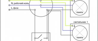
Operating principle of induction panels
The induction surface is a regular ceramic panel with induction coils located inside. In each of these coils, when turned on, an electromagnetic field is generated, which causes the movement of molecules in the bottom of the dishes installed on the panel. At the same time, the high speed of molecules generates heat, which is used for cooking. If you remove the cookware from the hob, the movement of molecules in its bottom stops.
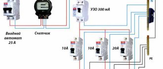
An induction surface from any manufacturer (AEG, Hansa, Gorenje, etc.) must be connected to a separate home electrical wiring line, which must be led directly from the switchboard and a specially installed machine. This line should end with a socket with a grounding contact, designed for a current of 32 to 40 A. The distance from the floor to the socket should be less than 0.9 m.
Important! To connect a surface with induction, it is prohibited to use existing sockets, the electrical cable to which is supplied from the kitchen junction box.
Before installing the induction hob and connecting it to the power supply, you must determine:
- its location:
- connection diagram;
- contents of delivery.
Connecting an Electrolux hob 4 wires
Some models of Electrolux, Bosch, Hansa, Gorenje brand hobs have a four-wire wire. Therefore, it can be very difficult to decide where to connect them if there are only 3 wires in the apartment.
Electrolux brand hobs already come with a wire. This makes the installation process easier, but in this case you need the correct connection diagram.
Using special instructions, you can connect the Electrolux hob yourself
A four-core cable consists of the following wires: neutral, ground and two phases. To properly connect the wire to the hob, you need to know some nuances.
Installing a 4-wire hob:
- Find the location where the terminals are located. They are usually located on the back of the case. Unlike Bosch brand panels, Electrolux has a plastic body. To open it, you just need to pry off the cover with a screwdriver.
- Look for the ground output in the open box; it is usually yellow-green in color. Near this output there should be a jumper for two wires. Phase wires are inserted into it; they are black and brown. To do this, you need to check the screws with a screwdriver, insert a jumper and tighten everything.
- When connecting the plug, you will only need to use the brown wire, and the black one will need to be insulated with a heat pipe.
All further actions when you connect two-phase equipment are carried out in exactly the same way as you would connect a single-phase electrical panel.
Requirements for the installation location of the hob
Before purchasing an induction hob, a potential buyer must determine the location where it will be placed. It is necessary to install an outlet not far from the selected zone, for which you will have to lay a separate line and connect it to a protective grounding device (RCD) . Also, when choosing a location, you must consider the following requirements.
- The panel must be placed on a flat surface without any distortions. The most popular installation location is above the oven, but in compliance with the manufacturer's recommendations.
- There should be enough space around the panel for ventilation, since overheating of the device can lead to its failure. In this case, the induction surface is located at a distance of at least 75 cm from the hood. You also need to provide a gap of several centimeters between the back wall of the slab and vertical surfaces (wall, etc.).
- The hob should not be placed directly above the dishwasher.
Selecting a power cable
When choosing the cable required to connect the induction cooker to the power supply network, you need to remember that according to the current SP31-110-2003 “Code of Rules for Design and Construction. Design and installation of electrical installations of residential and public buildings”, to connect electric stoves in residential buildings, it is necessary to use three-core copper cables with a core cross-section of at least 6 mm2. For this purpose, the domestic cable type VVGnG-Ls or its foreign analogue NYM is best suited.
If the connecting cable is not included in the delivery of the induction hob, then it must be selected based on the power that the latter consumes. The recommended cross-section of the connecting cable type VVGnG-Ls is given in the table below:
| Induction panel power, kW | Diameter of the copper core of the VVGnG-Ls cable, mm | Trip current of automatic load switch, A |
| up to 3.5 | 2,5 | 16 |
| from 3.5 to 5.5 | 4,0 | 25 |
| from 5.5 to 7.2 | 6,0 | 32 |
| from 7.2 to 8.8 | 10,0 | 40 |
Advice! When choosing a cable to connect an induction panel to the electrical network, you need to focus on the type of power outlet. Depending on the number of contacts in it, a cable with the corresponding number of cores is also purchased.
After selecting and purchasing the required cable, it must be equipped with a power plug and connected to the induction hob. In this case, the length of the cord should exclude both its strong tension and excessive sagging . But first you need to draw a separate line and install the appropriate socket or connect the stove in another way.
Connection
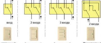
Be sure to note that the induction hob can be connected to 220 and 380 V networks:
- If the network is single-phase, then when connecting, use a special jumper, which is placed between the phase contacts.
- To connect a 4-core cable to a point with 3 terminals, you need to twist the black and brown cables together and connect them to the phase network wire.
The power outlet used to connect the appliance must be rated for a current of 25 A and the power of the appliance. In addition, it must be grounded. It is also necessary that the socket and plug match each other.
Important! The use of adapters and extension cords is unacceptable. To avoid additional switching, you can connect the device to the meter using a separate line.
Connection with or without a socket
A specialized socket can be either three- or four-pin. An appropriate plug is also selected for it, with the help of which the induction panel is connected to the electrical network.
Attention! The user’s apartment can have two types of electrical wiring: three-phase with a voltage of ~380 V and single-phase with a voltage of ~220 V. The choice of electrical outlet connection diagram depends on the type of electrical wiring in the apartment.
Having laid the electrical cable from the apartment distribution board to the installation site of the socket, it is connected to the latter through an RCD, which is selected based on the power of the induction surface.
If for one reason or another it is not possible to install an outlet, the induction panel is connected to the mains directly. This can be done in two ways.
- Connection using GML copper crimp sleeves, selected for the cross-section of the cable cores. The connection points must be insulated using heat-shrinkable tubing or insulating tape. All this should then be carefully hidden in the installation box (socket box). It is imperative to take into account the fact that special pressing pliers are required to crimp the sleeves - the use of pliers is prohibited.
- Connection via a terminal block installed in the socket box. In this case, you need a terminal block designed for the rated current of the connected panel.
Important! The induction cooking surface is connected to the power supply network through an RCD and an automatic load switch (differential circuit breaker) with a leakage current of 30 mA.
Hob connection process
Having decided on the method of connecting the induction surface to the electrical network, you need to do this by connecting the plug to the cable, and the latter directly to the panel.
Connecting the cable to the plug
In general, the cable must be connected to the power plug as follows. First you need to remove the insulation from the cable cores and disassemble the plug body. Then you should crimp the ends of the wires with NShV type lugs. Then you need to connect the ends of the wires to the contact terminals of the plug according to the diagram below (phase and neutral - under the outer terminals, grounding - under the top screw). Then the plug must be assembled, fixing the cable with the clamp provided in the housing.
However, the cables that come with hobs can be of 2 types: three- and four-core . If the number of wires in the cable matches the number of contacts of the plug-socket pair, then the connection does not cause problems - you just need to connect the colored wires to the corresponding contacts of the plug, based on the fact that:
- brown and black wires are connected to the phase contacts (L1-L3);
- The blue wire is connected to pin N (neutral or “0”);
- The yellow-green wire is connected to the PE (ground) contact.
If the cable coming from the induction panel has 4 cores, and the socket for connecting it has three contacts, then they are connected as follows:
- the black and brown wires are twisted together and connected to the “Phase” contact;
- The blue wire is connected to pin N;
- The yellow-green wire is connected to the PE grounding contact.
The user may also encounter a 5-core cable, originally designed for connecting high-power induction panels (more than 7 kW) to a three-phase network with a voltage of ~380 V. In this case, to connect to a ~220 V network:
- brown and black wires are twisted together and connected to the phase contact;
- the blue and gray wires are twisted together and connected to contact N (neutral or “0”);
- The yellow-green wire is connected to the PE (ground) contact.
If the power cable is connected to the induction surface, the latter can be installed in its designated place and connected to a power outlet.
Connecting the cable to the induction surface
In cases where the user needs to independently connect the cable to the hob, this can be done using the diagram located on its bottom side . Moreover, each panel is equipped with a special terminal block for connecting the power cable. Depending on the brand of induction hob, the cable connection is carried out differently.
For Bosch brand panels:
For Electrolux brand panels:
For Zanussi brand panels:
On a note! When connecting the induction panel to a single-phase power supply, the phase contacts of the terminal block (L1, L2, L3) are connected to each other using special jumpers included in the delivery kit.
To connect the cable to the hob you need to:
- remove the protective cover, thereby opening access to the terminals;
- install the cable clamp included in the delivery kit;
- run the cable through the cable clamp and align the wires with the terminals according to the connection diagram, with the ground wire (yellow-green) connected first, then the wires going to the neutral (blue and/or gray), and only after that the phase wires (brown) are connected and/or black);
- All screws are tightened, the strength of all connections is checked and the protective cover is returned to its place.
One day at work as an electrician: Correct connection of the hob
Good afternoon
Today we will talk about connecting a powerful modern hob to a ready-made cable outlet. Due to their high power, connecting such panels (often their power exceeds 6-7 kW) requires a separate line laid with a cable of at least 6 sq. mm (10 mm2 line options are rarely found).
There are two main ways to connect the hob:
1. Directly, that is, when laying, a supply of power cable is left, which is connected directly to the terminal block of the hob, or to a wire (depending on the model, hobs have either a terminal block or a wire).
2. Through a special power outlet rated, for example, 32 amperes:
Due to the high price of such sockets and plugs, the fact that the hob never turns off (and if it breaks, the socket does not provide any advantages - the stove can be turned off from the terminal block), the first method is most widespread. Let's consider it.
I bring out such a cable using a deep socket and a plug, for example, from the Etika series from Legrand, which allows you to arrange the hob cable outlet and the oven socket side by side in one frame.
And, of course, there are some nuances here. Hobs have either a terminal block or an outlet in the form of a flexible terminated wire. Often this wire is not part of the hob structure and can be disconnected from the terminal block without voiding the cooktop warranty. This was the case with the panel mentioned in the article.
In addition, almost all panels are designed for both single-phase and multi-phase (usually two-phase connection), and, judging by the designs of the panels, the manufacturer considers multi-phase connection as the main one, which is quite rare in Russian apartment buildings.
The consequence of this is that power cable manufacturers use 4 cores of 4 squares each and a panel junction box designed specifically for such a cable. Here is the cable, already disconnected from the hob:
The figure shows two-phase and single-phase connection diagrams for a Zanussi hob.
In the single-phase version, you need to connect a 6 mm2 cable to the panel, and this is where problems arise. The fact is that all cables intended for stationary installation (for example, VVGng-ls) have cores of flexibility class 1 according to GOST 22483-2012 (hereinafter referred to as monocores). Cables that have flexible (that is, having a flexibility class of 3 and higher according to GOST 22483-2012) conductors are not intended for stationary installation and have a short service life (that is, wiring with PVS or SHVVP wire is an obvious hack).
If the panel is equipped only with a terminal block, without a cable, it is extremely difficult to insert three 6 mm2 monocores into the junction box and connect there, and in addition, it is dangerous due to the rigidity of the cores - if bent, they can easily break the panel terminal block. If the cable is insulated and well made, it will not fit into the junction box at all.
It is extremely inconvenient to bend a monocore in a narrow space; it will “spring”, and if the outer insulation of the cable is not removed, then this is generally not easy. It should be understood that usually the oven is located under the hob and the distance from its back wall to the wall or back wall of the kitchen is very small.
If there is a “tail” wire, it must also be somehow connected to the power cable so that the connection is reliable, has low transition resistance, can withstand high currents and does not require periodic checking.
One solution is to disconnect the standard four-core cable (in this stove model it can be disconnected) and connect the hob with a flexible PugV wire and switch to a monocore supply cable using a high-quality permanent connection (pressure testing), which is discussed in this article.
The wire used is PugV 1×6 mm2 produced by the Kolchugino plant, purchased from Elektromontazh.
First, the PuGV wire is stretched a little in order to straighten it after not quite correct twisting in Electrical Installation:
The “curls” are cut off, leaving straight veins. Red was chosen as the color of the phase wire as it attracts attention and signals danger.
Next, the flexible wire for connection to the terminal block must be terminated. Typically, such a wire is terminated with SHNV or NShVI lugs (picture taken from the site techelectro.ru): NShV/NSHVI are good when you need to connect the wire to a full-fledged terminal block, such as, for example, in a circuit breaker or a screw / spring terminal, that is, where the tip is pressed evenly over the entire area.
In a hob, this is not entirely true - in all the panels I have seen, the core is clamped with a screw and a washer, and the washer does not cover the entire area of the tip.
In the case of using NShVI or NShV, the result is approximately the following:
The pressure washer greatly deforms the NShVI at the point of contact, which is not at all good. And this is especially bad since the tip also usually presses the jumper between adjacent terminals. Therefore, the tip at the connection point must be rigid, have a small thickness and a large surface area.
These conditions are best met by flat insulated pin tips of the NSHPI type (picture taken from the website www.fortisflex.ru): Unfortunately, due to their size, NSHPI do not fit into the distribution box of most hobs, so they have to be “finished”, namely shortened pin and cut off part of the “skirt”.
The pin is cut to the length of the crimped old hob cable.
The “skirt” is cut in the same way:
Next, the wire is stripped:
The NSHPI is put on and crimped. Please note that usually the NSHPI is crimped with a double oval, but due to the shortening of the “skirt” it is necessary to use a matrix with indentation at a point.
Next, jumpers are installed, set according to a single-phase circuit, and the terminated wires are screwed in with a torque screwdriver. Unfortunately, I did not find recommended tightening torques for screws on Zanussi hobs, so the screwdriver was set to the standard torque for terminal blocks - 2 nm.
Here's what we ended up with:
Next, we take GML sleeves produced by the KVT plant: Since in this apartment the power cable for the hob has a cross-section of 10 mm2 (and not 6, as is usually done), the sleeves had to be taken with a cross-section of 10 mm2. Despite the fact that the PUGV for connection to the hob has a cross-section of 6 mm2. Therefore, when crimping, the sleeve must be “stuffed” to the desired cross-section. PUGV 1.5 mm2 cores folded in three are used as “packing”.
GML crimping with “stuffing”:
After cutting off the “stuffing” wire, you get a ready-to-install kit in the form of a hob with connected PUGV wires and GML sleeves pressed onto them:
The hole for the hob was carefully prepared by the kitchen installers.
I do not recommend entrusting the connection of the hob to kitchen installers, since these specialists understand perfectly well the installation of kitchens, but often do not know how to make a high-quality connection, which can be downright dangerous if the hob currents are high!
Often the stove wire is connected through a fire-hazardous polyethylene terminal block, which also requires periodic tightening of the screws.
Just like you shouldn’t trust engineering systems (including electrical) to plasterers and generalists. Everyone must do their job.
Preparing the cable outlet (3 cores of 10 mm2 each) for crimp connection:
Next, the connection is crimped and insulated with high-quality 3M Temflex electrical tape, as well as heat-shrinkable tubing with an adhesive layer.
After shrinking with a construction hairdryer, a neat and reliable connection is obtained:
The wire is carefully rolled up and secured, and the hob is installed in its place.
The hob is working, you can cook:
Thank you for your attention.
Installing a panel into a countertop
Most often, the type of hob in question is mounted in a kitchen unit above the oven. In this case, you first need to cut a corresponding hole in the tabletop. Its dimensions and shape are usually given in the operating instructions.
Advice! You can also mark the hole in this way - simply attach the panel to the back side of the tabletop and trace its internal elements with a pencil or marker.
Having carefully cut out the hole, it is advisable to cover its edges with a material that will prevent moisture from penetrating under the hob (silicone varnish, foil, etc.). After this, the tabletop can be put back in place.
Before installing the hob into the countertop, you also need to prepare it - stick adhesive tape to its inside . In some models, instead of adhesive tape, the kit includes special plasticine, which must be stuck around the perimeter of the hole cut in the tabletop.
At the final stage, the hob along with the power cable is inserted into the hole in the countertop and, for a clearer fixation, pressed down on all sides with a little force. The panel is attached to the surface using standard fasteners.
Checking the functionality of the connected panel
Having installed the induction surface in place and connected it to the mains, they begin to check its functionality. To do this, you need to turn on the panel by pressing the “Network” button, after which it should be activated within one second. Then, after a few more seconds, a short beep will sound to confirm that the induction hob is ready for use. Each of the cooking sectors is activated by a separate button, after pressing which you can begin to adjust the power level.
Attention! Within several hours of operation after turning on the induction hob for the first time, an unpleasant odor reminiscent of burnt rubber may appear, but this is not a defect.
In the future, the trouble-free operation of the hob depends on how much it:
- exactly installed;
- securely fastened;
- protected from overheating (depending on the efficiency of the hood).
So, the process of installing and connecting induction cookers was described above, depending on the type of electrical wiring (three-phase/single-phase) and the available equipment (sockets, copper sleeves, terminal block). It must be remembered that working with electricity requires special knowledge and skills, so before connecting the panel yourself, you should carefully weigh your strengths. For your own safety and efficient operation of the hob, in some cases it is better to invite a qualified specialist.
Connecting the hob to the mains
Electrically powered hobs (induction, glass-ceramic and spiral) have confidently entered the everyday life of modern people. The popularity of this kitchen equipment is due to its versatility, ease of settings and control, modern design and cost-effectiveness. Buying an electric hob is not a cheap pleasure, so many consumers, wanting to save on the services of a specialist, install the hob themselves. The main thing in this process is compliance with certain rules, which we will discuss below.
Currently, multi-storey buildings with economy-level apartments are most often rented to consumers without connection to the main gas network. This option significantly reduces the cost of real estate and increases the safety of living. Gas stoves are not used in this case. Instead, electric cookers, panels and ovens are installed. This type of equipment is also used on suburban real estate located in places where there are no gas pipelines, and the use of natural gas in cylinders is difficult and economically ineffective.
Under all the above conditions, electrical appliances for cooking, stewing and frying food are installed in the kitchens of apartments, houses and cottages. There are only two equipment options for these purposes: you can connect a full-fledged electric stove with an oven to the mains, but most consumers prefer to install hobs and ovens separately. This article is devoted to the installation and connection of any type of hob, both simple with resistance heating elements and induction panels.