Switches or switches: what to choose?
It can be difficult for beginners and ordinary buyers to choose the right device to control the lighting in a room. Switches and switches are practically the same in appearance; the difference lies in the connection diagram and further operation. Both of them serve for switching in an electrical circuit.
The most important difference is that switches break the created circuit, while pass-through switches create a transition from one circuit to the next. The former control light from one source, and the latter – from 2-3 places.
The main switch is most often installed in the following places:
- In the corridor. The structure is installed at two opposite ends of the room. When entering the corridor, the light is turned on using one device, and at the exit from it it is turned off by another.
- On the stairs. This method of installing pass-through switches is often used in apartment buildings and private high-rise buildings. They are located on several floors, and light flows are controlled from any of them. For example, you can turn on the light on the 1st floor, go up the stairs to the 2nd or 3rd floor, and turn it off there. Going back down, activate the switch on the 2nd floor and turn it off on the 1st.
- In the bedroom. The principle of operation is similar to the previous options: the light turns on at the entrance and turns off at the head of the bed. This laughter connection is popular in children's rooms, especially if the child does not like to wander in the dark.
There are many more examples of the use of pass-through switches. They can be installed in any residential or industrial premises. They simplify the lighting control circuit and save energy.
Why are pass-through switches needed?
Pass-through switches are a solution that has been successfully used in lighting installations for quite a long time. With their help, you can turn on and off the same lighting fixture from several points in the room. Thanks to this, for example, a person entering a corridor can turn on the light at the beginning and turn it off when leaving it in another part of this room.
There are other ways to simplify the control of light in different parts of the room (sensors, sensors), but the advantage of pass-through switches is ease of installation, reliable operation under any conditions and the relative cheapness of this solution.
Such methods are widely used both in country houses and in residential premises of apartment buildings. Depending on the habits and needs of the residents of the room, pass-through switches can be installed in corridors, at the entrance to rooms, near beds or rest areas, and in other places as desired.
Connecting a pass-through switch
Before making a pass-through switch in one of the rooms, you need to pay attention to the following important points:
- Connecting such a switch requires a three-core power cable VVGng-Ls 3*1.5 or NYM 3*1.5mm².
- The device itself must be of the appropriate type. The circuit will not work on standard switches. Therefore, when purchasing a design, check the number of contacts on the back of the device: standard designs with one key are equipped with 2 terminals (input and output from the circuit), and main ones are equipped with 3 (1 terminal on top and 2 on the bottom).
Now let's look at how to connect a pass-through switch according to a light control circuit from 2 places. The first step is to install the device in the electrical outlet. To do this, you need to carefully remove the overhead frames of the structure and the key itself; this will help you see the location of the contact terminals. Then the common link among them is determined. Many manufacturers place the circuit of pass-through switches directly on the products.
If there is no electrical diagram, then you can use a special tester that will help ring the circuit. You need to go through all the contacts one by one and stop at the one where the device will show “0” and make a long sound. This will be the common terminal to which the phase with the power cable is connected. The remaining 2 wires are connected to the remaining links. The order doesn't matter here. After this, the key and frame are returned to the switch and secured in the box under the socket.
With the switch, which will be located at the other end of the room, exactly the same procedure is carried out.
Design and principle of operation of a pass-through switch
Disassembled switching unit
This photograph with explanations will help you study the design of pass-through switches. To connect the wires, screw terminals (1.3) are installed here. A complex-shaped rocker arm (2) is installed in the recesses of the support platform (4), which ensures reliable fixation. But it remains possible to swing it using the transition element (6) installed in the cover (5). If you press on its upper part, the corresponding contacts will be closed, the current will flow along the path from the rocker arm through the clamp (2-1). After pressing down, the electrical circuit 2-3 will close.
Developers use different solutions, but the principle of operation of products in this group is as described above. The following explanations should be given for the given parts of the structure:
- Dielectric parts in standard household switches are designed for a maximum voltage of 250 V and a current of no more than 10 A. These restrictions must not be violated.
- During disassembly, you need to pay attention to the reference points, the places of contact of moving elements. They determine the durability of the device.
- When switching, the electric discharge has a destructive effect on the contact groups. If the quality is insufficient, they will quickly fail. The next negative factor is the formation of oxides on their surface, which can create an insulating layer.
Features of modern pass-through switches
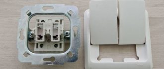
The central block discussed above is installed in a metal frame (6). This design uses special latches (4) for reliable fixation and speeds up installation operations. Other models use screw fastenings. Cutouts (1) in the frame make it easier to accurately locate switches, sockets of other electrical devices in one block horizontally/vertically.
When the screws (3) are tightened, special “legs” move out to the sides. They ensure that the pass-through switch is secured in the installation box. In this model, plate clamps (2) are installed, into which conductors stripped of insulation are inserted. High-quality contact is created without special tools and additional fasteners. This modification is equipped with built-in lighting. The light bulb is installed in such a way that replacement is possible without dismantling the entire mechanism.
A conventional device (1) and an illuminated switch (2) are connected to the circuit according to the same circuit
However, the second option ensures good visibility of the device in darkened rooms. It should be noted that this solution is not compatible with all types of lamps. When turned off, a small current passes through them. This will be enough to power the LEDs. Incandescent lamps and gas-discharge devices can be connected to such circuits without restrictions.
This photo clearly shows the “claws” that secure the product when installed inside the wall.
Front view
The following elements are indicated in the picture:
- Decorative frame (1). Some manufacturers produce a wide range of such products to match the appearance exactly to the aesthetics of a particular interior.
- The pressure plate (3) is designed to fix the frame.
- The keys (2) can be removed and reinstalled without special tools.
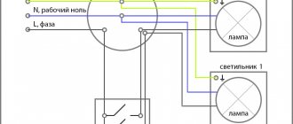
Typical connection diagram without a separate ground line
This figure will help you understand the principle of operation of a pass-through switch. In this position, the lamp (La1) is connected through the wiring box with a blue wire to the neutral conductor of the power supply network. The phase circuit is broken, so no current flows. If the first pass-through switch is moved to the down position, power will be supplied to the lamp. With a second device installed in a different location, you can return it to its original state.
Expert opinion
Igor Marmazov
ES, EM, EO design engineer (power supply, electrical equipment, interior lighting) ASP North-West LLC
Ask a specialist
“Please note that pass-through switches are installed in the phase conductor circuit. This rule must be applied in all electrical circuits to increase the level of safety.”
How to make a pass-through switch and install it correctly
Such homemade products are rarely used, since the modern retail network offers a wide range of various electrical products. However, it must be noted that there are a relatively smaller number of proposals for outdoor installation. If necessary, you can use the following instructions. It describes in detail how to make a pass-through switch from a regular one.
| Illustration | Actions and comments |
| This manual describes the process of converting a typical Schneider Electric single-gang switch. The symmetrical design of products from this brand is well suited for such work. Of course, it is permissible to transform devices from other manufacturers based on the principles outlined below. | |
| Disassembly of the switch is carried out carefully so as not to damage individual elements. Instead of a knife, as in the photo, you can use an unusable bank card or other device so as not to damage the plastic parts. | |
| After removing the keys, manually squeeze out the internal block. The body is set aside and the bottom cover is disconnected. | |
| Four latches are released sequentially on the side faces. Plastic strips and other special devices are also useful here. With their help, they maintain the integrity of connections that will be reused. | |
| After releasing the fasteners, remove the upper part. This frees up access directly to the workspace. | |
| The symmetry of the design makes it easy to move the contacts as desired without making significant changes. | |
| The contact plates are sequentially removed from the other switch and installed in the opposite direction. | |
| The second rod (marked in the photo) along with the spring is rearranged as needed. | |
| The previous operations are shown for clarity. In reality, the contact group of the base switch remains in place. Assembly of the structure will be performed in reverse order. | |
| To make a transition switch, install a jumper between the contacts, which are indicated by arrows. The red line marks a real electrical circuit, which is created by a wire with a yellow sheath inside the structure. This is the common contact of the switch (1). Numbers 2 and 3 indicate the outputs of the created pass-through switch. |
Next, the assembled block is installed in a metal frame, the key and other structural elements are secured.
This video shows how to install a pass-through switch together with an intermediate switch:
Related article: Carrying out installation operations yourself helps save time and money. This article discusses in detail the connection diagram of a two-key switch and installation technology.
This material, together with the information presented above, explains the need for a more careful familiarization with modifications of switching devices and connection diagrams. The following sections of the article provide the necessary information. After studying it, you can move on to a detailed description of installation operations.
Connection diagram for the pass-through switch wires in the distribution box
The next step is to correctly assemble the loop-through connection diagram in the junction box.
The distribution box includes the following three-core cables:
- wires from switches No. 1 and No. 2;
- cord from the automatic power panel;
- cable to a lighting device (chandelier, sconce).
Then, in order not to get confused in the connection of the cores, it is best to navigate by color. If the system uses a three-core VVG wire, the designation will be as follows:
- white or gray – phase;
- blue – zero;
- yellow-green – earth.
A second marking option is possible, where:
- white (gray) – phase;
- brown – zero;
- black - earth.
In cases where identifying wires is difficult, it is better to entrust the wiring diagram in the junction box to specialists. The performance of the circuit and the safety of the wiring in the room depend on this.
The first step is to combine the zero wires. To do this, using the terminals of the car, connect the corresponding wire from the input panel and the zero, which leads to the lighting device. The same procedure is repeated with the grounding conductors and connected to the chandelier body. Now all that remains is to connect the phase wires. The phase from the distribution panel is combined with the same conductor from switch No. 1.
After this, the common wire from main switch No. 2 is connected with a clamp to the cable phase, which is responsible for lighting.
At the last stage, the remaining secondary wires from the switches are connected to each other. The sequence doesn't matter. It is important to take into account the main connection rule: the phase from the distribution board must go to the common core of switch No. 1, and the same phase must go from switch No. 2 to the lighting device.
Only then will the connection diagram for a pass-through switch from 2 places work. Zero and ground are connected directly to the lamp.
What does a pass-through switch with 2 or more places look like?
This is the minimum number of devices that can be connected to the system so that the user can turn one lamp on or off. In practice, such devices are used to turn on the lighting at one point, walk a certain area in comfort, and turn off the light at another point without going back.
An example of a wiring device for a residential premises from the category of standard projects.
However, projects at control points are used quite actively. When you subsequently switch any of the switches, in any order, the lamp will turn off and on. As mentioned above, in the absence of a diagram, it is better to call the contacts at different positions of the key.
That is why the question arises, how to make it possible to turn on a light bulb from two or more places at once? Share with friends: You may also be interested. Let's consider the principle of operation of these devices according to the following photo: In this circuit, the following is mounted: power supply B phase and zero; distribution box in which switching is performed; 2 groups of lighting circuits, for example, this could be a chandelier and LED lighting in a hall or room. Control circuit for two separate lamps from four points As we have already noted, the lighting control circuit can be expanded endlessly. Of course, an additional wire can be laid in a cable channel or using a cavity in a plastic baseboard. As for cheap Chinese switches, basically there is no such circuit, so you have to connect the ends with a device. Automatic turning off of the light when leaving a certain area can be organized using timers or sensors that record movement.
Connecting a pass-through switch
The differences are in the number of contacts. The switch works as follows: when switching with a key, the input is connected to one of the outputs. All neutral and all protective wires are connected to two separate connectors. Multi-element schemes, of course, are of little use for the private residential sector, since projects of this kind rarely have long corridors or large rooms with several doors. Review of pass-through switch manufacturers: popular models Before you buy a pass-through switch, you should get acquainted with the leading manufacturers who produce the highest quality products. Let us next consider what the connection diagram for a pass-through switch from 2 places should be, since this is considered the most common option for implementing lighting systems in houses, apartments or offices.
In such situations, it becomes necessary to control lighting from two places; it is for solving such problems that the so-called pass-through switches are designed. The solution is made taking into account the wiring of the cable with the PE grounding conductor. In this case, we are talking about including a cross switch in the circuit, acting as an additional link. In this case, you can use the 4-point connection diagram for pass-through switches. After pressing the first button, the light will go out.
In the junction box we connect the corresponding wires of both switches. With this solution, it is already possible to walk through a long corridor halfway, turn off the lights on the completed half and turn on the lights on the remaining half. Review of pass-through switch manufacturers: popular models Before you buy a pass-through switch, you should get acquainted with the leading manufacturers who produce the highest quality products. There is no provision for an intermediate position in this case. A parallel switch, unlike a pass-through switch, contains as many as 5 contacts, which provide a more complex lighting control circuit, which has a much larger number of options. How to connect a pass-through switch
Lighting control circuit from 3 places
The scheme, in which there will be 3 or more switches for one lighting fixture, is slightly different from the standard version. A simple three-wire main switch will not help here. In the store you will need to purchase a rocker or cross switch, which is equipped with 4 outputs. It will act as an intermediate link between the main switches.
In the box you need to find 2 secondary wires from the main switches and connect them to the changeover device. The wire from 1 of the main device goes to the input of the intermediate device, and the wire coming out of it goes to 2 to the output terminals. In order not to confuse anything, you should always check the diagram that is drawn on the devices themselves. It happens that the entrance and exit to them are located on one side.
Only wires from a four-core cable are inserted into the junction box, and the device itself is located in any place convenient for the user. With a proper connection, the light will turn on and off from any installed device. You can add a variety of changeover switches to the circuit. The connection diagram for the main devices remains the same as for lighting from 2 places.
Failure by shorting and breaking
Touching the contacts when closing causes the spring-loaded terminal to be thrown back. With one switch on, several small rollbacks are observed, which together create vibration with a gradually decreasing amplitude. Subsequent contacts occur with shorter time and amplitude.
You might be interested in Calculating the resistance of parallel connections of resistors
Contact rejection is dangerous due to the appearance of a short electric arc, which provokes melting and evaporation of molecules. Violation of the working rhythm leads to an increase in the pressure of metal vapors, freezing of the contact, and an increase in the closing time.
During opening, the contact effect is considered zero. At the same time, the current density at the last junction increases and the junction resistance increases. The contact point melts, an isthmus appears between the moving parts, which also contributes to the appearance of a powerful electric arc. The phenomenon causes erosion of contacts, which occurs due to leaching of metal or its excessive adhesion.
Direct current in the circuit increases the intensity of material transfer from one terminal to another, this is due to the direction of the current in one direction, which does not change, as with alternating voltage. At low current, the contact isthmus ruptures at the positive terminal, and at the negative terminal the deposited metal hardens in the form of uneven tubercles. Erosion grows with increasing arc lifetime and increasing current strength.
Basic connection errors
The most common mistake is made at the stage of determining the common terminal. Some users believe that, regardless of the diagram, the correct link will be where there is only one contact. The circuit assembled in this way does not work correctly; the switches in it depend on each other. In this case, it is important to remember that on switches from different manufacturers the common terminal may be located in different places. Therefore, you should always check the provided diagram or call the links with a tester.
If everything is done correctly, but the circuit still does not work correctly, then the reason may be an incorrect choice of switch, perhaps there are simply 2 standard devices installed on the network.
The next popular installation mistake is incorrect introduction of intermediate devices into the circuit. Often 2 wires from switch No. 1 are connected to the input, and from switch No. 2 - both to the output. The circuit will not work, since the contacts must be connected crosswise. For such pass-through electrical switches, the connection diagram is almost always indicated on the device itself.
Disadvantages of loop-through connections
Despite all the advantages and ease of use of pass-through switches, the devices have several disadvantages:
- The devices do not have a precise position to determine whether they are active or inactive like standard switches. For example, if you need to replace a lamp in a room, it is almost impossible to determine by eye whether the power is on. In such situations, it is recommended to de-energize the room on the panel.
- There are too many wires in the junction box, which increases proportionally with the number of lighting devices in the circuit. Direct connection is not recommended as it increases cable consumption. For a large number of lamps in one circuit, the use of impulse relays is provided.
Connecting a pass-through switch to 2 points
Due to the need to use more wires, the complexity of the connection increases. The connection diagram is as follows. Phase and neutral are supplied to the junction box from the power source.
The zero wire is sent directly to the light source, and the phase to the switch. Inside the switch there is a division into 2 lines, which are sent further to the junction box and then go to the second switch. And after this, the wire is connected to the lamp.
It is possible to save on the amount of wire by connecting the “control” lines directly, but a competent electrician will not do this for the following reasons:
- connection using a junction box is more correct in connection with the requirements for electrical circuits;
- ease of repair. It is possible to test wires in sections to identify faults;
- will simplify the installation of connecting an additional switch.
Well-known manufacturers of pass-through electrical switches
The most common switches are products of the Legrand brand. The switches are made from high-quality materials, have a stylish, laconic design, are easy to install and are famous for their flexible pricing policy. The model range includes many offers - from cheap to expensive options. Among the disadvantages, users identified the need to adjust the installation location.
Lezard is a subsidiary of Legrand located in China. Lezard inherited only the design from his parent; the quality of the product and the materials used are significantly different from the original.
Another major player in the market is the Wessen brand, which is part of the Schneider Electric group of companies. Switches are manufactured according to the latest developments using new equipment and meet European quality standards. The devices allow for replacement of the switch frame without complete dismantling.
The Turkish manufacturer of devices for organizing an indoor electrical network, Makel, has been supplying the market with high-quality and safe switches, which in addition have a stylish design, for many years. Engineers have developed the ability to connect devices without interfering with the junction box, which simplifies the installation process and guarantees the safety of further operation.
Selecting a switch model and its installation
Modern consumer electronics stores offer a wide range of adapter switches. Regardless of the model, their connection diagram is similar, although there may be some nuances that are described in detail by the manufacturer in the instructions. The switch can have from one to three keys, depending on the features of your home's lighting system.
The easiest way to consider installing a system of two switches is using devices from the most popular manufacturer - the French company Legrand. The diagram for connecting these devices to the network is shown in Fig. 3. On it you can see that the two contacts that are located at the bottom of each switch are connected by two wires to their corresponding contacts on the second device. This is done by inserting a two-core wire into a junction box, in which they are twisted or soldered in pairs.